
Introduction
In this post, we’ll guide you through transforming your Arduino Uno into a fully functional Modbus RTU Server. This setup allows seamless reading of both Digital and Analog I/O using any Modbus Client. We’ll provide comprehensive, step-by-step instructions, including sample code and a detailed project demonstration. By the end of this tutorial, you’ll be able to effortlessly read Arduino’s Analog and Digital inputs using the Modbus Monitor XPF Program. (GitHub)
Source Code
You can download the source code for the Arduino Modbus RTU Server Program from GitHub. Check out the repositories: Modbus-Monitor and ArduinoModbusServer. Link: GitHub, Modbus-Monitor, ArduinoModbusServer
Arduino Sketch
- Start New Arduino Sketch Program or use example Blink program
- Program Arduino UNO as Modbus RTU Server using ArduinoModbus Open Source Modbus Library.
- #include <ArduinoModbus.h>
- Set pins in Arduino’s Setup Function:
- pinMode(ledPin, OUTPUT); //Pin 13 = LED with 1k Register
- pinMode(12, INPUT_PULLUP); //Pin 12 = DI //Connect GND To Turn OFF
- pinMode(11, INPUT_PULLUP); //Pin 11 = DI //Connect GND To Turn OFF
- pinMode(10, INPUT_PULLUP); //Pin 10 = DI //Connect GND To Turn OFF
- pinMode(9, INPUT_PULLUP); //Pin 09 = DI //Connect GND To Turn OFF
- pinMode(8, INPUT_PULLUP); //Pin 08 = DI //Connect GND To Turn OFF
- pinMode(7, INPUT); //Pin 07 = DI //Connect +5V To Turn ON
- pinMode(6, INPUT); //Pin 06 = DI //Connect +5V To Turn ON
- pinMode(5, INPUT); //Pin 05 = DI //Connect +5V To Turn ON
- pinMode(4, INPUT); //Pin 04 = DI //Connect +5V To Turn ON
- pinMode(3, INPUT); //Pin 03 = DI //Connect +5V To Turn ON
- pinMode(2, INPUT); //Pin 02 = DI //Connect +5V To Turn ON
- Configure Serial Port and Arduino Modbus Server in Setup section
- Serial.begin( BaudRate )
- ModbusRTUServer.begin( StationID, BaudRate )
- ModbusRTUServer.configureCoils(0x00, 14)
- ModbusRTUServer.configureDiscreteInputs(0x00, 14)
- ModbusRTUServer.configureInputRegisters(0x00, 10)
- ModbusRTUServer.configureHoldingRegisters(0x00,14);
- Map Digital Inputs, Digital Output, and Analog Output to Modbus Registers.
- See Source on GitHub for complete program.
- Example Read Digital Pin: coilValue = digitalRead( 2 ); //Read Pin 2
- Example Write to Modbus Server Coil: ModbusRTUServer.coilWrite( 0 , coilValue) //Write value to Modbus Server
- Example Read Analog Pin: holdingRegisterValue = analogRead( 0 ); //Read A0
- Example Write to Holding Register: ModbusRTUServer.holdingRegisterWrite( 0, holdingRegisterValue) //Write to Modbus Address 0 of Holding Register
void loop() {

  //declare variables
  int packetReceived;
  int pinval;
  int coilValue;

  //Just Blink Last State or Set to RUNNING
  StatusBlink(SERVER_STATUS_TYPE::RUNNING);

  //Poll for Modbus RTU requests
  ModbusRTUServer.poll();

  //Map the coil values to the discrete input values
  for (int i = 0; i < numCoils; i++) {

    //Modbus Map
    //00001 = LED_BUILTIN   DO (Digital OUT)
    //00002 = NOT USED      xxx
    //00003 = LED_BUILTIN   DI (Digital IN)
    //00004 = LED_BUILTIN   DI (Digital IN)


    //Map IO to Modbus Coils & Discrete Inputs starting with Modbus Address: 0 [000001]
    switch(i) {
      case 0: //Modbus Address=0, ModbusMonitor Address (1-based)= 000001
          //RX
        break;

       case 1: //Modbus Address=1, ModbusMonitor Address (1-based)= 000002
           //TX
        break;

        case 2: //Modbus Address=2,   ModbusMonitor Address (1-based)= 000003
        case 3: //Modbus Address=3,   ModbusMonitor Address (1-based)= 000004
        case 4: ...
        case 5: ...
        ...add more as needed

          coilValue = digitalRead(i);
          if(ModbusRTUServer.coilWrite(i,coilValue)) {
            //success
          } else {
            //failed
          }
        break;

      break;

      default:

      break;
    }

	//read value
    coilValue = ModbusRTUServer.coilRead(i);           //0x R/W

	//write value to Discrete Inputs
    ModbusRTUServer.discreteInputWrite(i, coilValue);   //1x RO
  }


  // map the holding register values to the input register values
  for (int i = 0; i < numHoldingRegisters; i++) {

   //Map IO to Modbus Coils & Discrete Inputs starting with Modbus Address: 0 [000001]
    switch(i) {

      case 0: //A0 = Modbus Address=0, ModbusMonitor Address (1-based)= 300001,  0 - 1023 for 0 to +5V
      case 1: //A1 = Modbus Address=1, ModbusMonitor Address (1-based)= 300002,  0 - 1023 for 0 to +5V
      case 2: ...
      ...add more as needed or see sample GitHub program
      case 5: //A5 = Modbus Address=5, ModbusMonitor Address (1-based)= 300006,  0 - 1023 for 0 to +5V
         holdingRegisterValue = analogRead(i);  //AI A0-A5, 0 to 1023
        break;

      default:
        holdingRegisterValue  = (long)ServerStatus;
      break;

    }

    if(ModbusRTUServer.holdingRegisterWrite(i, holdingRegisterValue)) {
      //success
    } else {
      //failed
    }

    holdingRegisterValue = ModbusRTUServer.holdingRegisterRead(i);  //4x R/W
    ModbusRTUServer.inputRegisterWrite(i, holdingRegisterValue);    //3x RO
  }
}

//See full source code at GitHub
Connect to Modbus Client
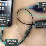
Connect the Arduino UNO to your Computer, compile the program, fix any errors, and upload your program. Note the COM port used by Arduino from Windows’ Device Manager.
- Read Modbus using the Modbus Monitor XPF or Modbus Monitor Advanced for Android
- Option 1: The pre-configured Modbus Map for this project can be downloaded from the Modbus Monitor XPF program‘s Online window. Click here to learn how to use the Online option.
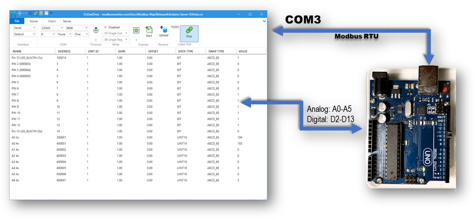
- Manual Entry: Add Register for each Modbus Address in the Arduino Program. For example, your program maps Pin 2 to Modbus Address 3 (one-based) of the Coil. This address translates to “000003” as the Address value and “BIT” as the data type. Similarly, the program Address is 400001 when your program maps A0 to the first Holding Register.
- Select and Configure the COM port in the Client (Tab) of the Modbus Monitor Program. Make sure the COM port and Configuration parameters of Arduino and Modbus Monitor XPF match. The sample program uses 9600, 8N1 as the default configuration.
- Click Start and note the values updating as the Arduino’s Analog and Digital values change. For example, the BUILDIN_LED PIN 13 should toggle between 1 and 0 at the Modbus Address “13” or “100013.”
- Questions? Use our Form and post it to the Android Server section, or contact us directly.